Antenna
for reducing
skywave interference
By Dr.
O. G. Villard, Jr.
Introduction
This article
describes a simple and compact means for converting standard book-size
battery- powered shortwave receivers to directional reception.
Such directivity can be used to reduce interference when the desired
and the interfering signals are coming from different directions.
The arrangement functions indoors as well as out, although better
outdoors. Construction is straightforward and can be done with
commonly available mechanical components. No modifications to
the radio are required for installation. There is some loss in
sensitivity, but the radio's normal tuning adjustments are unaffected.
Remember that is impossible to be predict exact results, but then
that is half the fun of antenna experimentation.
Father of
OTH radar
dies at 87

Oswald Garrison "Mike" Villard Jr., a professor emeritus
of electrical engineering and electronics pioneer in radio
and radar, died of pneumonia 7 January 2004 at a Palo Alto
nursing home.
He was 87.
One of Villard's biggest accomplishments was the development
of over-the-horizon radar. His biggest hobby was ham radio.
|
This report
was originally prepared by O. G. Villard for Dr. Kim Elliott of
the Voice of America's Office of Audience Relations. It is being
made available by Radio Netherlands as a service to listeners,
and a follow-up to a Media Network feature. SRI International
does research and development only.
Purpose
The following
has to do with an accessory for portable shortwave radios which
can weaken interfering signals (either distant or local) with
little effect on the desired broadcast. It can often restore program
clarity and understandability when reception is degraded by troublesome
co- or adjacent- channel interference. The essential arrangement
consists of a turntable, a metal plate, and a replacement-type
whip antenna.
Method
of operation
The device
makes reception poor in one or more directions although it remains
nearly normal in most others. Radio and accessories are rotated
on the turntable until the interfering signal is in a poor-reception
direction. If interfering and desired stations are adequately
separated in bearing, there should be only a small change in the
strength of the desired signal.
Requirements
(1) Interference
and desired signal must come from significantly different directions.
Only one interfering signal can be nulled at a time, unless two
or more such signals are coming from the same direction.
(2) Radio
must be compact and battery powered. External connections such
as headphones, tape recorder, or power supply cable (whether in
service or not) will cause poor performance and should not be
used.
(3) The assembly
must not be placed on - or immediately adjacent to - anything
metallic. Suitable supports are wooden tables or cardboard boxes.
(4) For best
results, the assembly should be spaced by 1 or 2 meters from wires
or large metal objects. Except when changing stations, the listener's
body should preferably be no closer than half a meter or so.
Features
(1) Easy
construction - can be home-built.
(2) Compact
in size - can be moved easily.
(3) Dimensions
not critical.
(4) Little
or no adjustments - except for antenna direction - required when
changing stations or bands.
(5) Functions
indoors although better outdoors.
Materials
needed
(1) One kitchen
turntable with tray made of wood or plastic, diameter equal to
or larger than that of the receiver. (A wooden turntable with
metal ballrace is fine.)
(2) One flat
piece of any kind of metal, same size or somewhat smaller than
the radio itself. Exact dimensions are not critical, but performance
degrades if the plate size is greater than that of the radio.
(3) A standard replacement-type telescoping whip antenna. Maximum
length should be somewhat longer than the radio's.
Assembly
instructions
(1) The additional
whip should be mounted vertically at one end of the (horizontal)
metal plate. The plate's end can be bent upward to provide a support.
The whip should be mounted in a position which makes it diagonally
opposite the set's own whip, wherever that may happen to be.
(2) The radio
is placed on the plate. Its weight and that of the plate itself
will usually stabilize the whip. If the radio has a ground terminal,
it should be connected to the plate. If not, connection can usually
be made to the outside of sockets into which recorder jacks, etc.,
are plugged. If the ground connection is omitted, performance
will be only slightly degraded.
(3) Plate
and radio rest on the turntable and are rotated together.
Operating
the antenna
(1) Select
the desired channel in the normal way.
(2) Extend
the radio's own whip to roughly its maximum length. Adjust the
additional whip to be about 20% longer.
(3) Rotate
the assembly (touching the plastic only; avoid the metal) until
the interfering signal is weaker than the desired signal. There
may be two positions where this is true; choose whichever position
is most satisfactory.
(4) For the
greatest interference reduction, adjust the length of the radio's
whip with respect to the external whip, or vice versa. Best results
are usually obtained when the external whip is appreciably longer
than the radio's whip.
(5) If signals
are very strong, it will help to shorten both whips in proportion.
Automatic gain control action with otherwise smooth out signal
strength changes due to antenna directivity.
(6) When
a deep null is achieved, the position of the listener's body may
affect its depth. This is particularly noticeable when the listener
stands close to the antenna in the direction of the station. The
effect is much less when the listener is so located that each
whip is roughly equally distant from the center of his body. When
the listener is half a meter or more from the whips, the effect
of body capacity can normally be ignored.
(7) Shortwave
signals of distant origin normally vary in strength with time
at a comparatively slow rate. This effect, called fading, can
make finding nulls difficult. The easiest way to determine the
true minimum strength direction(s) is to swing the turntable back
and forth reasonably rapidly on either side of a suspected null
position. The confusing effect of fading is then reduced because
the natural signal-strength changes are usually slower than the
rotation-caused ones.
Performance
(1) In the
right circumstances, the arrangement can produce nulls having
depths as much as 20 dB, which is usually adequate to separate
interfering stations.
(2) There
may be some variability in null depth with time, especially indoors.
If the null fills in, a slight change in turntable position will
usually restore its depth.
(3) Do not
expect this simple device to indicate actual station directions
accurately, especially indoors. It is designed to minimize one
interfering signal at a time by directive action without consideration
of signal bearing. However, it often does indicate approximate
bearing, especially when an average is taken.
(4) Due to
scatter propagation and/or ionospheric tilting, at any given time
there will usually be some skywave interfering stations that cannot
be significantly reduced in strength by compact directive antennas
of any kind. However, the fraction of nearby or ground-wave interfering
signals that can be reduced is much higher.
Troubleshooting
(1) Although
poor directionality is often a result of propagation and/or transmitter
beam heading, the problem can also be a local effect. If you suspect
this, try moving the assembly to a new location. A wooden stool
makes an excellent portable support. Unexpectedly poor results
may sometimes be caused by concealed metal for example, wooden
tables reinforced with a metal frame, metal mesh inside stucco
walls, etc.
(2) Sometimes
when a given station in a given direction can be nulled, other
stations in the same band will be found to have nulls in the same
direction no matter what the stations' true bearing. The result
is that interference is then reduced by the same amount as the
desired signal, just as if the source of the interference were
in the same direction as the desired signal. This effect is typically
encountered indoors and results from the presence of nearby metal
conductors which reradiate strongly. It can usually be reduced
by moving the assembly a few feet to a different indoor location.
However, in extreme cases it may be necessary to move outdoors.
The effect is worst in buildings of reinforced-concrete construction.
Two ways
to verify normal operation
(1) With
the direction of the assembly adjusted to null a given station,
touching either whip should make the received signal sharply increase
in amplitude, and by roughly the same amount.
(2) Remove
the external whip and the supporting metal plate, leaving the
receiver on the turntable with its whip in the normal vertical
position. Rotating the turntable should now have little or no
effect on signal strength. If there is a marked change, the radio
is very likely in a region where there are too many nearby reflecting
objects. Try moving to another location.
Possible
substitutions
(1) The metal
plate can be aluminum foil, if there is some other means for supporting
the whip. (Foil and whip should definitely be connected, and foil
and radio ground should also, if possible.)
(2) The `whip'
can be any kind of conductor, although length adjustability is
a great convenience. For example, it could consist of hookup wire
supported by a wooden dowel.
(3) A turntable
is quite desirable because of the ease with which it can be rotated.
However, an acceptable substitute is a flat slippery surface which
can be covered if needed with sheets of plastic or glossy magazine
covers. The radio and its whips could then be supported by a suitably-sized
piece of wood or plastic.
(4) A whip
that is too short can be extended by wrapping a length of bare
copper wire around its upper end.
Operation
outside the SW range
(1) The above
arrangement works at all frequencies at which the radio receives
through its whip. This is normally from 2 to 108 MHz. In the FM
band, signals must be kept weak to prevent the limiter from smoothing
out changes in amplitude. This can be done by detuning the receiver
and/or retracting the whips until background noise becomes audible
on the signal. Changes in noise level are then an indicator of
signal strength.
(2) Adding
an extra whip as above does not help in the MW broadcast band
because virtually all radios receive in that band via built-in
ferrite loops. However, the polar pattern of these loops also
contains nulls much like those of the whips discussed above. These
nulls can be used for interference reduction in the same general
way. Even skywave interference can sometimes be reduced by tilting
as well as rotating the radio. Supporting the radio in the reduced-interference
position (which is usually not horizontal) can be a problem. Soft
pillows have been used as adjustable supports for this purpose.
Modifications
for possibly improved performance
The detailed
behavior of the basic scheme described above depends on the set's
location. When null depth is inadequate, the additions of a length
of hookup wire (any size) attached to the end of the added whip
by any convenient means - for example, standard small-size alligator
clips. The wire behaves as an electrical extension of the added
whip and modifies its behavior.
Note the
small distance between the top of the radio's whip and the lowest
part of the added wire. There is a best spacing between these
two, which makes the null deepest and the off-null response greatest.
The length of either whip can be adjusted for this purpose, and
the adjustment is not critical. The K3MT version below shows a
piece of metal, adjustable in position, which effectively adds
capacity to the lower end of the radio's whip. It is convenient
to use aluminum or metal foil attached to and held in place an
inch or so above the top of the radio by a small clip. The clip
permits the metal to be swung out of the way when changing stations.
In many, but not all, situations, these additions have been found
to improve null depth when used singly or both at a time. Of the
two, the wire is the more helpful. Because of the variation in
radio shapes, and the characteristics of typical locations, the
improvement due to these devices cannot be guaranteed, but it
may be well worthwhile.
This document
is the latest in a series of articles describing different approaches
to indoor directional reception at HF. The approach described
herein is the simplest. Readers interested in the subject may
wish to consult the following publications:
1. O. G.
Villard, Jr., K. J. Harker and G. H. Hagn, "Interference-Reducing
Receiving Antennas for Shortwave Broadcasts", Voice Of America
Final Report on Project 1255, USIA Contract IA 22082-23, SRI International,
Menlo Park, CA (January 1987) (NTIS #PB88-188180/GAR)
2. O. G.
Villard, Jr., "Portable Unidirectional HF Aerial for Reducing
Co-Channel Multihop Sky-Wave Interference", Proceedings of the
Fourth International Conference on HF Radio Systems and Techniques,
April 11-14 1988, pp. 141-144, Institution of Electrical Engineers,
London, England (1988).
3. G. H.
Hagn, O. G. Villard, Jr., C. A. Hagn, and M. J. Toia, "The Wide-Strip
Horizontal Loop Antenna (HLA): An Effective Solution for Ground-Wave
Interference to Shortwave Reception," Proceedings of the Fourth
International Conference on HF Radio Systems and Techniques, April
11-14 1988, pp. 145-150, Institution of Electrical Engineers,
London, England (1988).
4. O. G.
Villard, Jr., "Interference-Reducing Antennas for Shortwave Broadcast
Listeners", IEEE Transactions on Broadcasting, Vol. 34, pp. 159-166
(June 1988).
5. O. G.
Villard, Jr., "The Coplanar-Twin-Loop Antenna", QST (American
Radio Relay League magazine), Vol. 72, No. 9, pp. 29-35 (September
1988).
6. Villard,
O. G. & R. Horvitz (editor), "Interference-Reducing Shortwave
Antennas", ANARC Newsletter, Vol. 25, No. 1-2, pp. 14-20 (December
1989/ January 1990).
7. Villard,
O. G. & R. Horvitz (editor), "Miniature Indoor Directional
Antennas for Reducing Sky-Wave and Ground-Wave Interference in
the Shortwave Bands", ANARC Newsletter, Vol. 26, No. 2-3, pp.
17-23 (February/ March 1990).
8. O. G.
Villard, Jr., "Combatting Interference in Shortwave Reception
with Compact, Indoor, Directive Antennas", World Radio & TV
Handbook, 1990 Edition, (Andrew Sennitt, Editor), pp. 547-553
(January 1990).

© This publication is copyright by Radio
Netherlands. Originally published August 1991.
The
K3MT version
Get a 2' x 2' base - plywood, cardboard, stiff foam plastic,
even the back of a wall-hung picture.
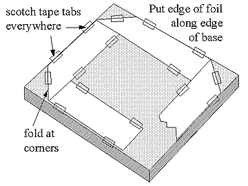
Cut a 6" wide piece of aluminum foil. Lay it on the base,
with its edge along the edge of the base. Make a 6 1/2" gap
in the corner where the foil begins. Then fold the foil over
itself as shown above.
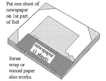
Cut a piece of newspaper 7" wide and 12" long -- or waxed
paper, handkerchief, whatever -- and tape it over the first
foil part.
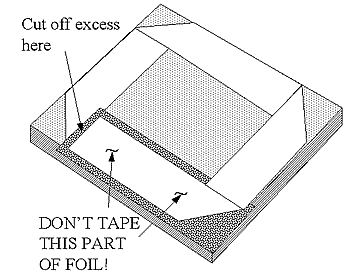
Leave the fifth flap of foil loose, cut off excess foil.
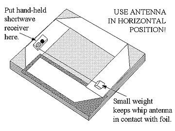
Put the receiver on the foil as shown, don't worry about electrical
connection. Pull the whip antenna out, use a small weight
to make sure the whip contacts the foil.
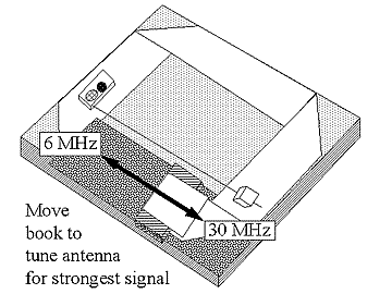
Tune the antenna to the right frequency by sliding the book
back and forth while keeping excess foil up and over the book.
Further details at K3MT
web. |
|


